This is an old revision of the document!
Table of Contents
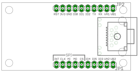
Netzer pin map
Overview
Pins of pin header JP1
| Name | Description |
|---|---|
| INT | GPIO pins, see IO for more information. |
| CLK | |
| MI | |
| MO | |
| CS | |
| IO4 | |
| IO5 | |
| IO3 | |
| VA2 | Connection for Power-over-Ethernet. That is the center tap of the Ethernet coil between RJ45 pins 3 and 6. |
| VB2 | Connection for Power-over-Ethernet. This pin is directly connected to the network jack of Netzer (RJ45 pins 7 and 8). |
Pins of pin header JP2
| Name | Description |
|---|---|
| RST | Use this pin to reset Netzer. The signal is low active (this means 0 resets Netzer). The Reset signal can also be used for waking up Netzer from sleep mode (after shut down). The pin is optional and can be left open. |
| 3V3 | Pin for power supply. Minimum voltage is 3.1 V. Maximum voltage is 3.6 V. |
| GND | Ground potential. |
| IO0 | GPIO pins, see IO for more information. |
| IO1 | |
| IO2 | |
| TX | |
| RX | |
| VA1 | Connection for Power-over-Ethernet. That is the center tap of the ethernet coil between RJ45 pins 1 and 2. |
| VB1 | Connection for Power-over-Ethernet. This pin is directly connected to the network jack of Netzer (RJ45 pins 4 and 5). |
Power-over-Ethernet (PoE)
The four connections VA1, VA2, VB1 and VB2 are connections from the network socket where a Power-over-Ethernet supply can be connected to.

The image shows an example circuit. Here the PoE supply AG9033 of Silver Telecom is used.


