Table of Contents
GPIO server
Settings
Via the GPIO server all IOs of Netzer can be addressed.
If the GPIO is activated, Netzer opens a TCP port (factory setting 65000) after restart. Activation and the port can be carried out by general settings via the website (see figure). The settings become directly effective!

For simple tests of the server and the protocol every terminal program may be used that is capable of building up connections via Raw TCP sockets, such as e.g. the Windows HyperTerminal.
Upon successful connection establishment, authentification takes place if activated. Otherwise, the protocol phase is directly entered into.
Protocol
In the GPIO server, a simple protocol is implemented.
Thanks to this protocol, digital inputs and outputs as well as ADC and PWM/pulse outputs can be read. Only digital outputs as well as PWM/pulse outputs can be written. Furthermore, these outputs must not be occupied by functions of the serial server.
Reading or writing is done by commands.
Invididual commands are separated from each other by Whitespaces (space characters, tab, word wrap etc. - all characters with the ASCII code ⇐ 32).
Each pin can be unambiguously addressed via its ID. Here an overview of all IDs:
| Name | IO0 | IO1 | IO2 | IO3 | IO4 | IO5 | TX | RX | SPI_CS | SPI_INT | SPI_CLK | SPI_MI | SPI_MO | All pins |
|---|---|---|---|---|---|---|---|---|---|---|---|---|---|---|
| ID | a | b | c | d | e | f | g | h | i | j | k | l | m | x |
Reading of pins works as follows:
a=?\n
Server reply: a=1

e=?\n
Server reply: e=03ff

m=?\n
Server reply: m=0

x=?\n
Server reply: x=0011
Depending on whether the pin is configured digital or as ADC/PWM, the GPIO servier supplies binary or numerical values.
The wildcard ID x always supplies the digital state of all pins, regardless of whether a pin supplies binary or numerical values. At bit level, the states of the individual pins as per the following table are possible:
| Bit 15 | Bit 14 | Bit 13 | Bit 12 | Bit 11 | Bit 10 | Bit 9 | Bit 8 | Bit 7 | Bit 6 | Bit 5 | Bit 4 | Bit 3 | Bit 2 | Bit 1 | Bit 0 |
|---|---|---|---|---|---|---|---|---|---|---|---|---|---|---|---|
| 0 | 0 | 0 | m | l | k | j | i | h | g | f | e | d | c | b | a |
Writing on pins is done analogously:
a=1 Server reply: a=1
d=0123 Server reply: d=0123
m=0 Server reply: m=0
x=0123 Server reply: x=0123
The wildcard ID x describes only the pins configured as digital outputs and not occupied by the serial server.
Events
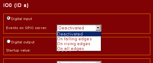
For every digital input, an event trigger may be activated on the GPIO configuration page.

Thus, the GPIO server independently sends protocol messages in the event of an accordingly configured amendment.
Edge counter
For the IO channels a, b, and c edge counters are implemented. They can be accessed via the special protocol ID z.
Reading the counter works like:
za=? Server response: za=0001
zb=? Server response: zb=0000
zc=? Server response: zc=0123
Counter values are transmitted as 16 bit hexadecimal numbers. The value itself is stored in the lower 15 bits. The MSB of the counter is the carry flag, which indicates a counter overrun or underrun. If carry flag is set it remains set until reset manually.
Also writing of counter values is possible:
za=0 Server response: za=0000
Change of counter values is not transmitted automatically. The user has to poll the server periodically to detect changes.


