The SPI slave protocol
For using the Netzer as Ethernet modem from i.e. another microcontroller the Netzer has the SPI slave mode implemented. TCP/IP connections can be established and released (as client or server) and data can be received and sent.Important note: Since version 1.4 the protocol and interface has significantly changed compared with prior versions. For older versions please check out the Elektor website.
Physical connection
At least six free pins on the master side are needed. See the diagramm for a typical connection.
All pins are read only for the GPIO access (GPIO webpage and GPIO service).
Connection example
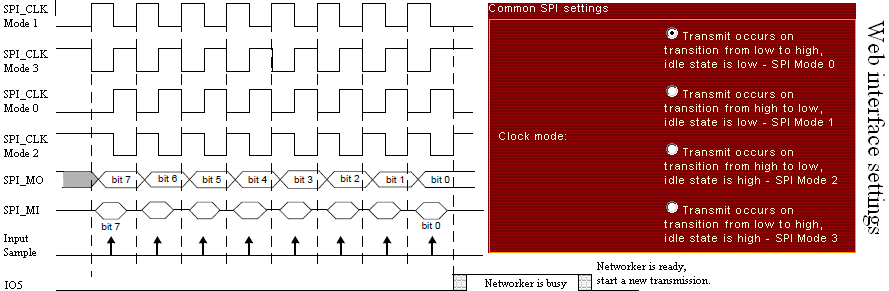
Waveforms
| Netzer pin | Direction | Description |
| SPI_CLK | Input | The master generates edges for data transmission here. One tranfer unit is eight edges and therefore eight bits. All clock polarities are supported by Netzer (settable via web interface). Important Note: The selected idle state on this pin is checked by Netzer on startup to ensure synchronicity with SPI master. Netzer blocks as long as the pin level does not match the idle state! |
| SPI_MO | Output / Open | Netzer shifts out its data on SPI_CLK edges. |
| SPI_MI | Input | Master shifts out its data on SPI_CLK edges. |
| SPI_CS | Input | The master MUST select Netzer with a low chip select line. During the entire transmission the chip select must stay low. Note: Releasing the chip select does not automatically reset the register interface (see below). A released chip select disables the internal SPI_MO driver. A pullup or pulldown resistor is needed therefore on this pin to prevent floating. |
| SPI_INT | Output | Netzer pulls this pin low, if internal states has changed. The master MUST check this line inbetween complete transmissions of eight bit. If the line is low the master MUST stop any pending register access immediately with a rising edge on IO1. The interrupt pin is released after a SPI master write to the interrupts flags register. |
| IO5 | Output | IO5 is used as handshake pin for increasing data throughput. The pin is low during master transmissions. On finished master transmissions the pin is driven high as soon as the Netzer internal SPI module has detected pending data. During the processing of the received byte the line stays high. If processing is finished and possible data is provided by the slave for shifting out the line returns to low. The master is not allowed to start a new transmission during the high state of IO5. |
| IO1 | Input | IO1 is used for controlling the register access. A falling edge on IO1 starts a new register access. Netzer awaits the very next byte from master after the edge as register address. A rising edge on the pin stops the register access. For easier connection the SPI_CS pin and IO5 can connected together. |
The protocol
Two commands, register read and register write, are supported. The first byte after a falling edge on IO1 is the address and control byte which is transmitted by the SPI master.
| Bit 7 | Bit 6 - Bit 0 |
| 0 = Read access 1 = Write access | Register address |
The returned byte from Netzer is a dummy byte and MUST be ignored by the master. After this address and control byte 0-n bytes may be transmitted by master till the IO1 pin is reset to 1.
Write access is performed with 0-n bytes after the address and control byte. The transfered bytes are written to the addressed register. Normally all the bytes are acknowledged by Netzer with a non zero value in return. Consider that a received byte deals with the prior written byte - not with the current one. Writing more than one byte to a register address is important for the socket data registers (see below).
Read access is performed with 1-n dummy bytes after the address and control byte. The returned bytes from Netzer (excluding the first one as mentioned above) are the read bytes from the requested register address. Reading more than one byte from a register address is important for the socket data registers (see below).
The virtual register set
The communication with Netzer takes place via a virtual register set.
This overhead is processed in software. For the protocol a virtual register set is implemented. The whole SPI communication is based on this registers.
| Register address | Register name | Access | Description | |||||||||||||||||||||||||||||||||
| 0x00 | Interrupt flags | RW | Read out this register while interrupts are pending (SPI_INT=0). The flags in this register determine the interrupt source. When no interrupt is pending the content of this register is 0. Writing to this register (any value or none) resets the pending interrupt (SPI_INT=1). Here are the flags:
| |||||||||||||||||||||||||||||||||
| 0x01 | Netzer state | RW | Read access delivers the current state of Netzer:
Write access executes commands on Netzer. Here are the supported commands:
| |||||||||||||||||||||||||||||||||
| 0x02 | Netzer socket state | RW | Read access delivers the socket flags:
Write access executes commands on Netzer:
| |||||||||||||||||||||||||||||||||
| 0x03-0x05 | Reserved | |||||||||||||||||||||||||||||||||||
| 0x06 | Firmware-Version: Build (low) | R | ||||||||||||||||||||||||||||||||||
| 0x07 | Firmware-Version: Build (high) | R | ||||||||||||||||||||||||||||||||||
| 0x08 | Firmware-Version: Minor | R | ||||||||||||||||||||||||||||||||||
| 0x09 | Firmware-Version: Major | R | ||||||||||||||||||||||||||||||||||
| 0x0A-0x0F | MAC address | R | The Netzer MAC address as six byte array. | |||||||||||||||||||||||||||||||||
| 0x10-0x14 | IP address | R | The Netzer IP address as four byte array. | |||||||||||||||||||||||||||||||||
| 0x14-0x18 | Reserved | |||||||||||||||||||||||||||||||||||
| 0x18-0x1B | Remote IP address | RW | Read access: In Server mode the read value is only valid if connected. Write access: Only for client mode: Enter the IP address of the remote node to connect. | |||||||||||||||||||||||||||||||||
| 0x1C-0x1D | Port | RW | The data format is little endian! Server mode: Writing the port where the server should listen on. Do this BEFORE configuring Netzer as server! 0 (default) takes the web interface configured port. Client mode: Writing the port of the remote node to connect. | |||||||||||||||||||||||||||||||||
| 0x1E | Reserved | |||||||||||||||||||||||||||||||||||
| 0x1F | Socket data | RW | If Netzer is connected via TCP/IP with remote node it uses two internal (ring) buffer. The receive buffer and the send buffer. They have a size of 256 bytes each. Writing to the socket data address writes data to the receive buffer. Netzer automatically sends data from receive buffer via TCP/IP if connected. If the RX_BUFFER_FULL flag is set the SPI master has to stop transfering data and wait for a cleared RX_BUFFER_FULL. Reading from socket data address sequentially reads from the send buffer. The transmit buffer is automatically filled with incoming TCP/IP packets. The SPI master should read out the send buffer only if the TX_DATA_PENDING flag is set! |